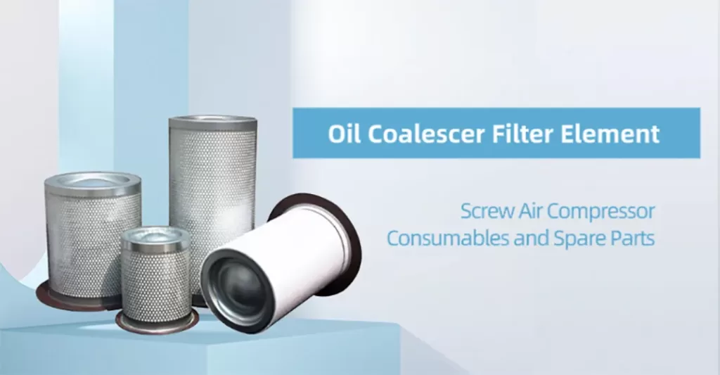
The oil-gas separator filter element separates the oil-air mixture compressed and output by the air compressor’s main unit. It uses a micron-grade glass fiber layer to separate oil droplets from the compressed air, coalescing them into larger droplets. Under gravity, the lubricating oil collects at the bottom of the oil separator and returns to the compressor’s lubrication system via the return oil pipe. This separation can achieve sub-micron levels, ensuring the compressed air’s oil content is less than 3 ppm.
II. Core Functions
1. Efficient Separation: Separates the vast majority (over 99.9%) of the lubricating oil from the mixture, allowing it to return to the lubrication system for reuse.
2. Air Purification: Ensures the discharged compressed air has extremely low oil content (typically below 3 ppm, with high-quality filter elements achieving 2 ppm or even below 1 ppm), meeting downstream air requirements.
3. Reduced Oil Consumption: Separation efficiency directly determines the lubricant topping-up intervals for the air compressor. High-efficiency separation significantly reduces oil consumption, saving operational costs.
III. Importance
A failed or inefficient oil separator filter element can lead to:
· Oil Carryover: Large amounts of lubricating oil enter the downstream air network and equipment with the compressed air, causing abnormal lubricant consumption and requiring frequent topping up.
· Equipment Contamination: Oil contaminates dryers, downstream filters, clogs pipes, and damages pneumatic tools, spray painting equipment, precision instruments, etc.
· Product Defects: In industries like food, pharmaceuticals, and electronics, oil contamination can lead to product spoilage, causing significant economic losses.
· Increased Energy Consumption: A clogged filter element causes excessive pressure drop, requiring the compressor to operate at higher power to reach the target pressure, increasing electricity consumption.
IV. Structure of the Oil-Gas Separator Filter Element
1. Filter Media: The core is specially treated micro-glass fiber filtration material. This material features high porosity, high dirt holding capacity, and specific surface properties conducive to oil droplet coalescence.
2. Support Core: A central metal mesh tube provides support, preventing the filter media from collapsing.
3. End Caps: Upper and lower end caps, typically metal, securely bond the filter media and support core together using special sealant, ensuring sealing.
4. Sealing Components: An O-ring or metal seal ring is fitted at the top to ensure an absolute seal between the element and the separator vessel cover, preventing oil-air mixture from bypassing separation.
V. Working Principle: Coalescing Separation
The separation process is not simple “filtration” but a complex physical process:
1. Primary Separation: The mixture first impacts the walls of the separator vessel. Due to changes in velocity and direction, most liquid oil is initially separated by centrifugal force and gravity, settling down.
2. Fine Separation: The remaining compressed air, containing numerous tiny oil droplets (in aerosol form, particle size < 1µm), passes from the inside out through the filter media.
· Interception: Larger droplets are directly intercepted on the fiber surfaces.
· Inertial Impaction: As the airflow changes direction, oil droplets collide with fibers due to inertia.
· Diffusion: Very small droplets undergo Brownian motion, randomly diffusing to fiber surfaces where they are adsorbed.
· Coalescence (Most Critical): Captured tiny oil droplets continuously merge and coalesce on the fibers, eventually forming larger droplets.
3. Gravity Settling: When the coalesced oil droplets become large enough, their weight exceeds the buoyant force of the rising gas and the adsorption force of the fibers. They then drip down under gravity to the bottom of the separator vessel, returning to the lubrication system.
Finally, almost oil-free compressed air collects on the external side of the filter element and passes through the minimum pressure valve to the aftercooler and air pipeline.
VI. Replacement Cycle and Judgment Criteria
There is no fixed replacement schedule for oil separator filter elements; replacement must be based on actual conditions.
· The separator vessel is usually equipped with a differential pressure sensor, or the filter element top has a delta P indicator (a red pointer).
· The element must be replaced immediately when the pressure drop exceeds 0.8 – 1.0 bar (or refer to the compressor manufacturer’s specification).
· Hazards of Excessive Pressure Drop: Increased energy consumption, reduced air output, and in severe cases, causing the safety valve to activate or the filter element to collapse.
· Other Replacement Indicators:
1. Abnormal Lubricant Consumption (“Oil Carryover”): After ruling out other causes (e.g., clogged return line, improper installation), this is often the primary indicator of filter element failure.
2. Significant Drop in Compressed Air Quality: Detection of oil contamination in downstream equipment.
3. Operating Hours: Often used as a reference, typically between 3000-8000 hours, but strongly recommended to base replacement primarily on pressure differential.
VII. Industry Applications
The oil-gas separator filter element is a key component in industrial equipment used for separating gas from liquid in lubricating oil, primarily applied in solid-liquid, gas-solid, and gas-liquid separation processes within industries like petroleum, chemicals, metallurgy, and aviation. Materials used include glass fiber, polypropylene fiber, and activated carbon fiber. Among these, glass fiber is widely used in the petrochemical industry due to its high-temperature and corrosion resistance.
The global filtration equipment industry is undergoing rapid transformation, driven by evolving environmental regulations, technological advancements, and growing demand across sectors like manufacturing, healthcare, and...
The global filtration industry, a cornerstone of sectors from automotive to pharmaceuticals, faces unprecedented pressure as raw material costs fluctuate at historic rates. Stainless steel,...
As nations worldwide intensify efforts to combat climate change and reduce industrial pollution, 2025 marks a pivotal year for environmental policy updates—particularly in the European...
Bridging—also known as the “bridging phenomenon”—is a common challenge in industrial filtration, where particles accumulate on filter media, forming a dense layer that blocks flow...
Selecting the optimal filter media is critical to achieving efficient, cost-effective, and long-lasting filtration. However, with countless materials available—from stainless steel mesh to epoxy-coated screens—the...
Excessive backwashing is a red flag in industrial filtration, signaling inefficiencies that inflate operational costs, strain equipment, and shorten filter lifespans. For industries relying on...